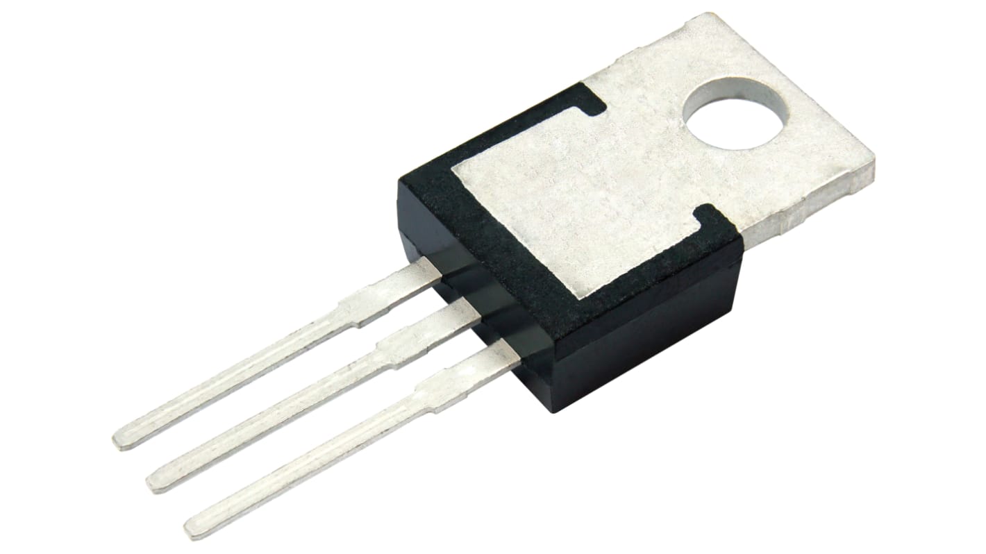
Vishay SIHP Type N-Channel MOSFET, 34 A, 650 V Enhancement, 3-Pin TO-220AB SIHP085N60EF-GE3
- RS Stock No.:
- 268-8317
- หมายเลขชิ้นส่วนของผู้ผลิต / Mfr. Part No.:
- SIHP085N60EF-GE3
- ผู้ผลิต:
- Vishay

รูปภาพประกอบสินค้าเป็นเพียงรูปภาพใกล้เคียงเท่านั้น กรุณาอ่านรายละเอียดสินค้า
มีส่วนลดเมื่อซื้อจำนวนมาก
ดูตัวเลือกการกำหนดราคาในการซื้อปริมาณมากยอดรวมย่อย (1 หลอด หลอดละ 50 ชิ้น)*
THB7,288.40
(ไม่รวมภาษีมูลค่าเพิ่ม)
THB7,798.60
(รวมภาษีมูลค่าเพิ่ม)
ส่งฟรีหากซื้อเกิน ฿2,500.00
สต็อกสุดท้ายของ RS
- 1,000 ชิ้นสุดท้ายพร้อมจัดส่งจากคลังสินค้าต่างประเทศ
ชิ้น | ต่อหน่วย | ต่อหลอด* |
|---|---|---|
| 50 - 50 | THB145.768 | THB7,288.40 |
| 100 - 450 | THB141.395 | THB7,069.75 |
| 500 - 950 | THB135.739 | THB6,786.95 |
| 1000 + | THB128.952 | THB6,447.60 |
*ตัวบ่งบอกราคา / price indicative
- RS Stock No.:
- 268-8317
- หมายเลขชิ้นส่วนของผู้ผลิต / Mfr. Part No.:
- SIHP085N60EF-GE3
- ผู้ผลิต:
- Vishay
คุณสมบัติ / Specifications
ข้อมูลทางเทคนิค / Technical Data Sheets
Legislation and Compliance
รายละเอียดสินค้า / Product Details
ค้นหาผลิตภัณฑ์ที่คล้ายกันโดยเลือกคุณลักษณะอย่างน้อยหนึ่งรายการ
เลือกทั้งหมด | คุณลักษณะ | ค่า |
|---|---|---|
| Brand | Vishay | |
| Channel Type | Type N | |
| Product Type | MOSFET | |
| Maximum Continuous Drain Current Id | 34A | |
| Maximum Drain Source Voltage Vds | 650V | |
| Series | SIHP | |
| Package Type | TO-220AB | |
| Mount Type | Through Hole | |
| Pin Count | 3 | |
| Maximum Drain Source Resistance Rds | 0.084Ω | |
| Channel Mode | Enhancement | |
| Typical Gate Charge Qg @ Vgs | 63nC | |
| Minimum Operating Temperature | -55°C | |
| Forward Voltage Vf | 1.2V | |
| Maximum Power Dissipation Pd | 184W | |
| Maximum Operating Temperature | 150°C | |
| Standards/Approvals | RoHS | |
| Automotive Standard | No | |
| เลือกทั้งหมด | ||
|---|---|---|
Brand Vishay | ||
Channel Type Type N | ||
Product Type MOSFET | ||
Maximum Continuous Drain Current Id 34A | ||
Maximum Drain Source Voltage Vds 650V | ||
Series SIHP | ||
Package Type TO-220AB | ||
Mount Type Through Hole | ||
Pin Count 3 | ||
Maximum Drain Source Resistance Rds 0.084Ω | ||
Channel Mode Enhancement | ||
Typical Gate Charge Qg @ Vgs 63nC | ||
Minimum Operating Temperature -55°C | ||
Forward Voltage Vf 1.2V | ||
Maximum Power Dissipation Pd 184W | ||
Maximum Operating Temperature 150°C | ||
Standards/Approvals RoHS | ||
Automotive Standard No | ||
- COO (Country of Origin):
- CN
Vishay SIHP Series MOSFET, 650V Maximum Drain Source Voltage, 34A Maximum Continuous Drain Current - SIHP085N60EF-GE3
This MOSFET is a high‑voltage N‑channel transistor designed for power switching in industrial and electronic systems. It operates across a wide temperature range and is supplied in a through‑hole TO‑220AB package for straightforward mounting and thermal management. The device is suited to applications requiring controlled high‑voltage switching and substantial continuous current handling.
Features and Benefits:
• 650V rating enables high‑voltage switching applications • 34A continuous drain current supports heavy‑load operation • 0.084Ω on‑resistance reduces conduction losses • 184W power dissipation allows elevated power handling • 63nC typical gate charge permits predictable drive requirements • 150°C maximum junction temperature sustains high‑temperature operation
Applications
• Suitable for industrial motor drive switching stages • Ideal for switch‑mode power supply high‑voltage switches • Used for power conversion in automation control systems • Can be used for inverter front‑end switching modules • Suitable for laboratory test rigs requiring through‑hole mounting
What gate drive considerations should I account for?
With a typical gate charge of 63nC at Vgs, ensure the gate driver can source and sink sufficient current to achieve the required switching speed while controlling EMI.
How does the package influence thermal design?
The TO‑220AB through‑hole format enables easy attachment to a heatsink and a straightforward thermal path for managing up to 184W dissipation under proper heatsinking conditions.
What operating environment range does it tolerate?
The device functions from -55°C up to a maximum operating temperature of 150°C, permitting use in both cold‑start and elevated‑temperature installations.
How should I protect the device from overvoltage events?
Since the transistor has a maximum drain‑source voltage of 650V and a gate limit of 30V, include appropriate snubbers, clamp diodes or transient suppressors and ensure gate drive never exceeds the gate‑source limit.
ลิงก์ที่เกี่ยวข้อง
- Vishay SIHP Type N-Channel MOSFET 650 V Enhancement, 3-Pin TO-220AB SIHP085N60EF-GE3
- Vishay SIHP Type N-Channel MOSFET 650 V Enhancement, 3-Pin TO-220AB SIHP054N65E-GE3
- Vishay SIHP Type N-Channel MOSFET 650 V Enhancement, 3-Pin TO-220AB SIHP074N65E-GE3
- Vishay SIHP Type N-Channel MOSFET 650 V Enhancement, 3-Pin TO-220AB SIHP150N60E-GE3
- Vishay SIHP Type N-Channel MOSFET 600 V Enhancement, 3-Pin TO-220AB SIHP155N60EF-GE3
- Vishay EF Type N-Channel Power MOSFET 650 V Enhancement, 3-Pin TO-247AC SIHG085N60EF-GE3
- Vishay SIHB Type N-Channel MOSFET 650 V Enhancement, 3-Pin TO-263 SIHB085N60EF-GE3
- Vishay EF Type N-Channel Power MOSFET 650 V Enhancement, 3-Pin TO-247AC