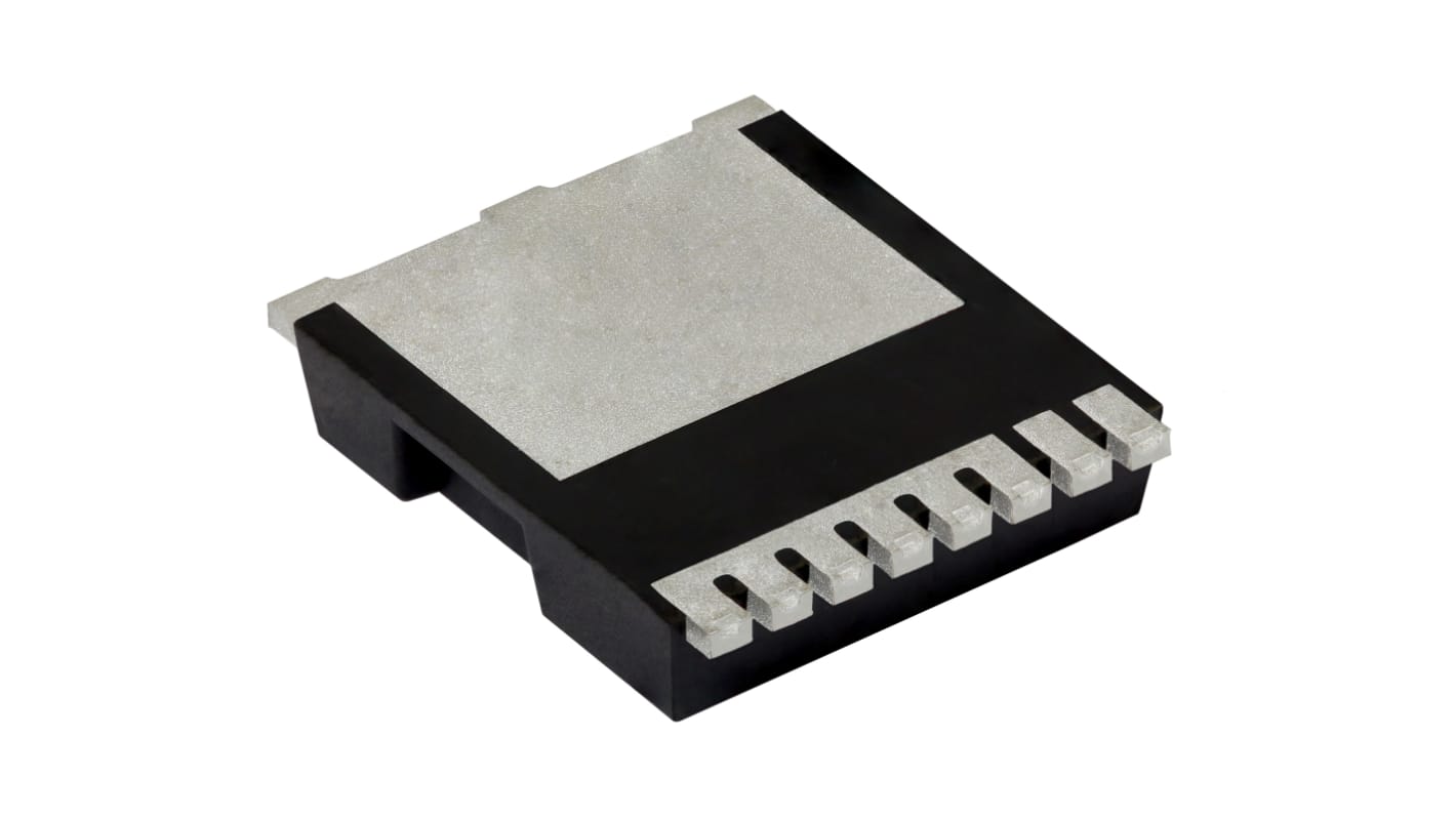
Vishay SIHK Type N-Channel MOSFET, 21 A, 650 V Enhancement, 8-Pin PowerPAK 10 x 12 SIHK125N60EF-T1GE3
- RS Stock No.:
- 268-8313
- หมายเลขชิ้นส่วนของผู้ผลิต / Mfr. Part No.:
- SIHK125N60EF-T1GE3
- ผู้ผลิต:
- Vishay

รูปภาพประกอบสินค้าเป็นเพียงรูปภาพใกล้เคียงเท่านั้น กรุณาอ่านรายละเอียดสินค้า
มีส่วนลดเมื่อซื้อจำนวนมาก
ดูตัวเลือกการกำหนดราคาในการซื้อปริมาณมากยอดรวมย่อย (1 แพ็ค แพ็คละ 2 ชิ้น)*
THB345.48
(ไม่รวมภาษีมูลค่าเพิ่ม)
THB369.66
(รวมภาษีมูลค่าเพิ่ม)
ส่งฟรีหากซื้อเกิน ฿2,500.00
มีในสต็อก
- เพิ่มอีก 1,996 ชิ้นจะส่งได้หลังจากวันที่ 03 สิงหาคม 2569 ไปอีกประมาณ 7 วันทำการ
ต้องการสินค้าเพิ่มหรือไม่ ระบุจำนวนและคลิก ‘ตรวจสอบวันจัดส่ง’ เพื่อดูข้อมูลเพิ่มเติมเกี่ยวกับสต็อกสินค้าและการจัดส่ง
ชิ้น | ต่อหน่วย | ต่อแพ็ค* |
|---|---|---|
| 2 - 48 | THB172.74 | THB345.48 |
| 50 - 98 | THB155.395 | THB310.79 |
| 100 - 248 | THB127.295 | THB254.59 |
| 250 + | THB124.85 | THB249.70 |
*ตัวบ่งบอกราคา / price indicative
- RS Stock No.:
- 268-8313
- หมายเลขชิ้นส่วนของผู้ผลิต / Mfr. Part No.:
- SIHK125N60EF-T1GE3
- ผู้ผลิต:
- Vishay
คุณสมบัติ / Specifications
ข้อมูลทางเทคนิค / Technical Data Sheets
Legislation and Compliance
รายละเอียดสินค้า / Product Details
ค้นหาผลิตภัณฑ์ที่คล้ายกันโดยเลือกคุณลักษณะอย่างน้อยหนึ่งรายการ
เลือกทั้งหมด | คุณลักษณะ | ค่า |
|---|---|---|
| Brand | Vishay | |
| Product Type | MOSFET | |
| Channel Type | Type N | |
| Maximum Continuous Drain Current Id | 21A | |
| Maximum Drain Source Voltage Vds | 650V | |
| Package Type | PowerPAK 10 x 12 | |
| Series | SIHK | |
| Mount Type | PCB | |
| Pin Count | 8 | |
| Maximum Drain Source Resistance Rds | 0.125Ω | |
| Channel Mode | Enhancement | |
| Typical Gate Charge Qg @ Vgs | 45nC | |
| Maximum Power Dissipation Pd | 132W | |
| Minimum Operating Temperature | -55°C | |
| Forward Voltage Vf | 1.2V | |
| Maximum Operating Temperature | 150°C | |
| Standards/Approvals | RoHS | |
| Length | 9.9mm | |
| Automotive Standard | No | |
| เลือกทั้งหมด | ||
|---|---|---|
Brand Vishay | ||
Product Type MOSFET | ||
Channel Type Type N | ||
Maximum Continuous Drain Current Id 21A | ||
Maximum Drain Source Voltage Vds 650V | ||
Package Type PowerPAK 10 x 12 | ||
Series SIHK | ||
Mount Type PCB | ||
Pin Count 8 | ||
Maximum Drain Source Resistance Rds 0.125Ω | ||
Channel Mode Enhancement | ||
Typical Gate Charge Qg @ Vgs 45nC | ||
Maximum Power Dissipation Pd 132W | ||
Minimum Operating Temperature -55°C | ||
Forward Voltage Vf 1.2V | ||
Maximum Operating Temperature 150°C | ||
Standards/Approvals RoHS | ||
Length 9.9mm | ||
Automotive Standard No | ||
- COO (Country of Origin):
- CN
Vishay SIHK Series MOSFET, 650V Maximum Drain Source Voltage, 21A Maximum Continuous Drain Current - SIHK125N60EF-T1GE3
This MOSFET is a high-voltage N-channel switching transistor designed for power conversion and control on printed circuit boards. It suits demanding electrical and electronic systems where elevated drain-to-source voltage handling and substantial current capability are required. The device is supplied in a Compact PowerPAK 10x12 package for PCB mounting and is intended for applications that operate across a wide temperature range.
Features and Benefits:
• 650V drain-to-source rating enables high-voltage switching
• 21A continuous drain current supports heavy load duty
• 0.125Ω Rds(on) reduces conduction losses at operating current
• 45nC typical gate charge allows efficient gate-drive management
• 132W power dissipation permits substantial thermal loading
• 21A continuous drain current supports heavy load duty
• 0.125Ω Rds(on) reduces conduction losses at operating current
• 45nC typical gate charge allows efficient gate-drive management
• 132W power dissipation permits substantial thermal loading
Applications
• Suitable for industrial motor drive inverter stages
• Ideal for high-voltage power supplies in automation systems
• Used for switch-mode power conversion in electrical equipment
• Can be used for medium-power traction and conversion modules
• Ideal for high-voltage power supplies in automation systems
• Used for switch-mode power conversion in electrical equipment
• Can be used for medium-power traction and conversion modules
What voltage stress can it withstand in switching circuits?
It can handle up to 650V between drain and source, making it appropriate for high-voltage topologies.
How does gate-charge affect drive design?
A typical gate charge of 45nC informs gate-driver current and switching-loss calculations during transition events.
What thermal extremes can it operate within?
Operational limits span from -55°C at the low end to 150°C at the high end for junction temperatures.
How many pins and what mounting style does it use?
It is an 8-pin device intended for PCB mounting in a PowerPAK 10x12 footprint.
What is the maximum permissible gate voltage?
The gate may be driven up to 30V relative to source without exceeding its gate‑source rating.
ลิงก์ที่เกี่ยวข้อง
- Vishay SIHK Type N-Channel MOSFET 650 V Enhancement, 8-Pin PowerPAK 10 x 12 SIHK125N60EF-T1GE3
- Vishay SIHK Type N-Channel MOSFET 650 V Enhancement, 8-Pin PowerPAK 10 x 12 SIHK185N60EF-T1GE3
- Vishay SIHK Type N-Channel MOSFET 650 V Enhancement, 8-Pin PowerPAK 10 x 12 SIHK105N60EF-T1GE3
- Vishay SIHK Type N-Channel MOSFET 650 V Enhancement, 8-Pin PowerPAK 10 x 12 SIHK045N60EF-T1GE3
- Vishay SIHK Type N-Channel MOSFET 650 V Enhancement, 8-Pin PowerPAK 10 x 12 SIHK085N60EF-T1GE3
- Vishay SIHK Type N-Channel MOSFET 650 V Enhancement, 8-Pin PowerPAK 10 x 12 SIHK105N60E-T1-GE3
- Vishay SIHK Type N-Channel MOSFET 600 V Enhancement, 8-Pin PowerPAK 10 x 12 SIHK155N60EF-T1GE3
- Vishay SIHK Type N-Channel MOSFET 600 V Enhancement, 8-Pin PowerPAK 10 x 12 SIHK155N60E-T1-GE3