Vishay SIHK Type N-Channel MOSFET, 16 A, 650 V Enhancement, 8-Pin PowerPAK 10 x 12 SIHK185N60EF-T1GE3
- RS Stock No.:
- 268-8316
- หมายเลขชิ้นส่วนของผู้ผลิต / Mfr. Part No.:
- SIHK185N60EF-T1GE3
- ผู้ผลิต:
- Vishay

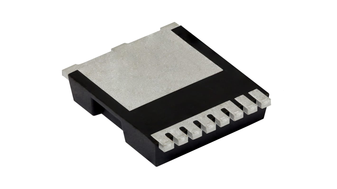
รูปภาพประกอบสินค้าเป็นเพียงรูปภาพใกล้เคียงเท่านั้น กรุณาอ่านรายละเอียดสินค้า
มีส่วนลดเมื่อซื้อจำนวนมาก
ดูตัวเลือกการกำหนดราคาในการซื้อปริมาณมากยอดรวมย่อย (1 แพ็ค แพ็คละ 2 ชิ้น)*
THB343.43
(ไม่รวมภาษีมูลค่าเพิ่ม)
THB367.47
(รวมภาษีมูลค่าเพิ่ม)
ส่งฟรีหากซื้อเกิน ฿2,500.00
มีในสต็อก
- เพิ่มอีก 2,000 ชิ้นจะส่งได้หลังจากวันที่ 03 สิงหาคม 2569 ไปอีกประมาณ 7 วันทำการ
ต้องการสินค้าเพิ่มหรือไม่ ระบุจำนวนและคลิก ‘ตรวจสอบวันจัดส่ง’ เพื่อดูข้อมูลเพิ่มเติมเกี่ยวกับสต็อกสินค้าและการจัดส่ง
ชิ้น | ต่อหน่วย | ต่อแพ็ค* |
|---|---|---|
| 2 - 48 | THB171.715 | THB343.43 |
| 50 - 98 | THB154.475 | THB308.95 |
| 100 - 248 | THB126.54 | THB253.08 |
| 250 - 998 | THB124.11 | THB248.22 |
| 1000 + | THB97.15 | THB194.30 |
*ตัวบ่งบอกราคา / price indicative
- RS Stock No.:
- 268-8316
- หมายเลขชิ้นส่วนของผู้ผลิต / Mfr. Part No.:
- SIHK185N60EF-T1GE3
- ผู้ผลิต:
- Vishay
คุณสมบัติ / Specifications
ข้อมูลทางเทคนิค / Technical Data Sheets
Legislation and Compliance
รายละเอียดสินค้า / Product Details
ค้นหาผลิตภัณฑ์ที่คล้ายกันโดยเลือกคุณลักษณะอย่างน้อยหนึ่งรายการ
เลือกทั้งหมด | คุณลักษณะ | ค่า |
|---|---|---|
| Brand | Vishay | |
| Product Type | MOSFET | |
| Channel Type | Type N | |
| Maximum Continuous Drain Current Id | 16A | |
| Maximum Drain Source Voltage Vds | 650V | |
| Package Type | PowerPAK 10 x 12 | |
| Series | SIHK | |
| Mount Type | PCB | |
| Pin Count | 8 | |
| Maximum Drain Source Resistance Rds | 0.193Ω | |
| Channel Mode | Enhancement | |
| Forward Voltage Vf | 1.2V | |
| Minimum Operating Temperature | -55°C | |
| Typical Gate Charge Qg @ Vgs | 32nC | |
| Maximum Power Dissipation Pd | 114W | |
| Maximum Operating Temperature | 150°C | |
| Standards/Approvals | RoHS | |
| Length | 9.9mm | |
| Automotive Standard | No | |
| เลือกทั้งหมด | ||
|---|---|---|
Brand Vishay | ||
Product Type MOSFET | ||
Channel Type Type N | ||
Maximum Continuous Drain Current Id 16A | ||
Maximum Drain Source Voltage Vds 650V | ||
Package Type PowerPAK 10 x 12 | ||
Series SIHK | ||
Mount Type PCB | ||
Pin Count 8 | ||
Maximum Drain Source Resistance Rds 0.193Ω | ||
Channel Mode Enhancement | ||
Forward Voltage Vf 1.2V | ||
Minimum Operating Temperature -55°C | ||
Typical Gate Charge Qg @ Vgs 32nC | ||
Maximum Power Dissipation Pd 114W | ||
Maximum Operating Temperature 150°C | ||
Standards/Approvals RoHS | ||
Length 9.9mm | ||
Automotive Standard No | ||
- COO (Country of Origin):
- CN
Vishay SIHK Series MOSFET, 650V Drain Source Voltage, 16A Continuous Drain Current - SIHK185N60EF-T1GE3
This MOSFET is a high-voltage N-channel transistor designed for power switching on PCB assemblies. It operates across a wide temperature range and suits industrial control and power-conversion environments where robust voltage handling and thermal tolerance are required.
Features and Benefits:
• 650V drain voltage enables high-voltage switching applications • 16A continuous drain current supports substantial load currents • 0.193Ω low Rds(on) reduces conduction losses and heat generation • 114W power dissipation allows sustained power handling • 32nC typical gate charge supports moderately fast switching speeds • 30V maximum gate drive permits flexible gate-control designs
Applications
• Suitable for high-voltage power converters and inverters • Ideal for switch-mode power supplies in industrial systems • Used for motor drive switching in automation equipment • Can be used for lighting ballast and electronic transformer control
What thermal extremes can it tolerate in system design?
It is specified to operate down to -55°C and up to 150°C, allowing use in environments with wide ambient temperature variation.
What mounting considerations are needed on a PCB?
It is intended for PCB mounting in a PowerPAK 10x12 package with eight pins, so PCB layout should provide adequate thermal vias and copper area for heat spreading.
How should gate drive be limited to protect the device?
The gate must not exceed ±30V relative to the source, so gate-drive circuitry should include clamping or regulation to prevent overvoltage.
What charge characteristic affects gate-driver selection?
The typical gate charge is 32nC at the specified gate bias, informing the required drive current and switching losses for gate-driver sizing.
ลิงก์ที่เกี่ยวข้อง
- Vishay SIHK Type N-Channel MOSFET 650 V Enhancement, 8-Pin PowerPAK 10 x 12 SIHK185N60EF-T1GE3
- Vishay SIHK Type N-Channel MOSFET 650 V Enhancement, 8-Pin PowerPAK 10 x 12 SIHK045N60EF-T1GE3
- Vishay SIHK Type N-Channel MOSFET 650 V Enhancement, 8-Pin PowerPAK 10 x 12 SIHK105N60EF-T1GE3
- Vishay SIHK Type N-Channel MOSFET 650 V Enhancement, 8-Pin PowerPAK 10 x 12 SIHK085N60EF-T1GE3
- Vishay SIHK Type N-Channel MOSFET 650 V Enhancement, 8-Pin PowerPAK 10 x 12 SIHK125N60EF-T1GE3
- Vishay SIHK Type N-Channel MOSFET 600 V Enhancement, 8-Pin PowerPAK 10 x 12 SIHK155N60EF-T1GE3
- Vishay SIHK Type N-Channel MOSFET 650 V Enhancement, 8-Pin PowerPAK 10 x 12 SIHK105N60E-T1-GE3
- Vishay SIHK Type N-Channel MOSFET 600 V Enhancement, 8-Pin PowerPAK 10 x 12 SIHK155N60E-T1-GE3