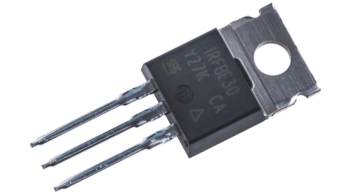
Vishay IRFBE30 Type N-Channel Power MOSFET, 4.1 A, 800 V Enhancement, 3-Pin TO-220AB IRFBE30PBF
- RS Stock No.:
- 541-1124
- Distrelec หมายเลขบทความ:
- 171-15-208
- หมายเลขชิ้นส่วนของผู้ผลิต / Mfr. Part No.:
- IRFBE30PBF
- ผู้ผลิต:
- Vishay

รูปภาพประกอบสินค้าเป็นเพียงรูปภาพใกล้เคียงเท่านั้น กรุณาอ่านรายละเอียดสินค้า
มีส่วนลดเมื่อซื้อจำนวนมาก
ดูตัวเลือกการกำหนดราคาในการซื้อปริมาณมากยอดรวมย่อย (1 ชิ้น)*
THB68.03
(ไม่รวมภาษีมูลค่าเพิ่ม)
THB72.79
(รวมภาษีมูลค่าเพิ่ม)
ส่งฟรีหากซื้อเกิน ฿2,500.00
มีในสต็อก
- เพิ่มอีก 137 ชิ้นจะส่งได้หลังจากวันที่ 03 สิงหาคม 2569 ไปอีกประมาณ 7 วันทำการ
- เพิ่มอีก 1,382 ชิ้นจะส่งได้หลังจากวันที่ 07 สิงหาคม 2569 ไปอีกประมาณ 7 วันทำการ
ต้องการสินค้าเพิ่มหรือไม่ ระบุจำนวนและคลิก ‘ตรวจสอบวันจัดส่ง’ เพื่อดูข้อมูลเพิ่มเติมเกี่ยวกับสต็อกสินค้าและการจัดส่ง
ชิ้น | ต่อหน่วย |
|---|---|
| 1 - 12 | THB68.03 |
| 13 - 64 | THB66.67 |
| 65 + | THB54.87 |
*ตัวบ่งบอกราคา / price indicative
- RS Stock No.:
- 541-1124
- Distrelec หมายเลขบทความ:
- 171-15-208
- หมายเลขชิ้นส่วนของผู้ผลิต / Mfr. Part No.:
- IRFBE30PBF
- ผู้ผลิต:
- Vishay
คุณสมบัติ / Specifications
ข้อมูลทางเทคนิค / Technical Data Sheets
Legislation and Compliance
รายละเอียดสินค้า / Product Details
ค้นหาผลิตภัณฑ์ที่คล้ายกันโดยเลือกคุณลักษณะอย่างน้อยหนึ่งรายการ
เลือกทั้งหมด | คุณลักษณะ | ค่า |
|---|---|---|
| Brand | Vishay | |
| Channel Type | Type N | |
| Product Type | Power MOSFET | |
| Maximum Continuous Drain Current Id | 4.1A | |
| Maximum Drain Source Voltage Vds | 800V | |
| Series | IRFBE30 | |
| Package Type | TO-220AB | |
| Mount Type | Through Hole | |
| Pin Count | 3 | |
| Maximum Drain Source Resistance Rds | 3Ω | |
| Channel Mode | Enhancement | |
| Maximum Gate Source Voltage Vgs | 20V | |
| Maximum Power Dissipation Pd | 125W | |
| Typical Gate Charge Qg @ Vgs | 78nC | |
| Forward Voltage Vf | 1.8V | |
| Minimum Operating Temperature | -55°C | |
| Maximum Operating Temperature | 150°C | |
| Length | 10.41mm | |
| Height | 9.01mm | |
| Width | 4.7mm | |
| Standards/Approvals | RoHS | |
| Automotive Standard | No | |
| เลือกทั้งหมด | ||
|---|---|---|
Brand Vishay | ||
Channel Type Type N | ||
Product Type Power MOSFET | ||
Maximum Continuous Drain Current Id 4.1A | ||
Maximum Drain Source Voltage Vds 800V | ||
Series IRFBE30 | ||
Package Type TO-220AB | ||
Mount Type Through Hole | ||
Pin Count 3 | ||
Maximum Drain Source Resistance Rds 3Ω | ||
Channel Mode Enhancement | ||
Maximum Gate Source Voltage Vgs 20V | ||
Maximum Power Dissipation Pd 125W | ||
Typical Gate Charge Qg @ Vgs 78nC | ||
Forward Voltage Vf 1.8V | ||
Minimum Operating Temperature -55°C | ||
Maximum Operating Temperature 150°C | ||
Length 10.41mm | ||
Height 9.01mm | ||
Width 4.7mm | ||
Standards/Approvals RoHS | ||
Automotive Standard No | ||
Vishay IRFBE30 Series Power MOSFET, 800V Drain Source Voltage, 4.1A Continuous Drain Current - IRFBE30PBF
This power MOSFET is a through‑hole N‑channel transistor designed for switching and power control in industrial electronics. It operates as an enhancement‑mode device suitable for high‑voltage applications, offering a combination of voltage handling and gate‑drive capability for demanding electrical systems.
Features and Benefits:
• 800V drain‑source voltage enables high‑voltage switching applications • 4.1A continuous drain current supports moderate load currents • 3 Ω maximum Rds reduces current loss during conduction • 78 nC typical gate charge allows predictable switching behaviour • 125W power dissipation manages thermal stress in power circuits • -55 °C to 150 °C operating range endures wide temperature extremes
Applications
• Suitable for high‑voltage power supplies and converters • Ideal for industrial motor drive switching stages • Used for solid‑state relay and protection circuitry • Can be used for load switching in automation panels
What gate voltage limits should I observe during design?
Gate drive must remain within ±20V maximum relative to source to prevent gate‑oxide stress.
How should thermal management be approached on a PCB?
Use a heatsink on the TO‑220AB package or a thermally conductive mounting solution to dissipate up to 125W of power under rated conditions.
What switching characteristics affect EMI in my design?
The typical gate charge of 78 nC at the specified gate drive influences rise and fall times, impacting switching transitions and electromagnetic emissions.
Is this device suitable for surface‑mounting techniques?
It is supplied in a TO‑220AB through‑hole package intended for mechanical mounting and conventional through‑hole assembly.
ลิงก์ที่เกี่ยวข้อง
- Vishay IRFBE30 Type N-Channel Power MOSFET 800 V Enhancement, 3-Pin TO-220AB
- Vishay Single 1 Type N-Channel Power MOSFET 800 V, 3-Pin TO-262 IRFBE30LPBF
- Vishay Single 1 Type N-Channel Power MOSFET 800 V, 3-Pin TO-262
- Vishay E Type N-Channel Power MOSFET 800 V Enhancement, 3-Pin TO-220AB SIHP15N80AE-GE3
- Vishay E Type N-Channel Power MOSFET 800 V Enhancement, 3-Pin TO-220AB
- Vishay EF Type N-Channel Power MOSFET 800 V Enhancement, 3-Pin TO-220AB SIHP11N80AEF-GE3
- Vishay EF Type N-Channel Power MOSFET 800 V Enhancement, 3-Pin TO-220AB
- DiodesZetex Isolated 2 Type N-Channel Power MOSFET 60 V Enhancement, 8-Pin SOIC DMN6070SSD-13