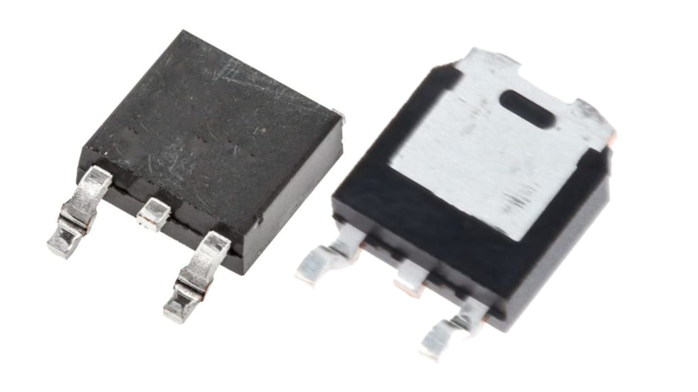
Vishay IRFR9014 Type P-Channel Power MOSFET, -5.1 A, -60 V, 3-Pin TO-252 IRFR9014PBF
- RS Stock No.:
- 256-7313
- หมายเลขชิ้นส่วนของผู้ผลิต / Mfr. Part No.:
- IRFR9014PBF
- ผู้ผลิต:
- Vishay

รูปภาพประกอบสินค้าเป็นเพียงรูปภาพใกล้เคียงเท่านั้น กรุณาอ่านรายละเอียดสินค้า
มีส่วนลดเมื่อซื้อจำนวนมาก
ดูตัวเลือกการกำหนดราคาในการซื้อปริมาณมากยอดรวมย่อย (1 แพ็ค แพ็คละ 10 ชิ้น)*
THB200.28
(ไม่รวมภาษีมูลค่าเพิ่ม)
THB214.30
(รวมภาษีมูลค่าเพิ่ม)
ส่งฟรีหากซื้อเกิน ฿2,500.00
มีในสต็อก
- 2,820 ชิ้นพร้อมจัดส่งจากคลังสินค้าต่างประเทศ
ต้องการสินค้าเพิ่มหรือไม่ ระบุจำนวนและคลิก ‘ตรวจสอบวันจัดส่ง’ เพื่อดูข้อมูลเพิ่มเติมเกี่ยวกับสต็อกสินค้าและการจัดส่ง
ชิ้น | ต่อหน่วย | ต่อแพ็ค* |
|---|---|---|
| 10 - 10 | THB20.028 | THB200.28 |
| 20 - 40 | THB19.624 | THB196.24 |
| 50 - 90 | THB19.22 | THB192.20 |
| 100 - 490 | THB15.619 | THB156.19 |
| 500 + | THB12.904 | THB129.04 |
*ตัวบ่งบอกราคา / price indicative
- RS Stock No.:
- 256-7313
- หมายเลขชิ้นส่วนของผู้ผลิต / Mfr. Part No.:
- IRFR9014PBF
- ผู้ผลิต:
- Vishay
คุณสมบัติ / Specifications
ข้อมูลทางเทคนิค / Technical Data Sheets
Legislation and Compliance
รายละเอียดสินค้า / Product Details
ค้นหาผลิตภัณฑ์ที่คล้ายกันโดยเลือกคุณลักษณะอย่างน้อยหนึ่งรายการ
เลือกทั้งหมด | คุณลักษณะ | ค่า |
|---|---|---|
| Brand | Vishay | |
| Channel Type | Type P | |
| Product Type | Power MOSFET | |
| Maximum Continuous Drain Current Id | -5.1A | |
| Maximum Drain Source Voltage Vds | -60V | |
| Package Type | TO-252 | |
| Series | IRFR9014 | |
| Mount Type | Surface | |
| Pin Count | 3 | |
| Maximum Drain Source Resistance Rds | 0.5Ω | |
| Maximum Gate Source Voltage Vgs | 20V | |
| Maximum Power Dissipation Pd | 25W | |
| Typical Gate Charge Qg @ Vgs | 12nC | |
| Minimum Operating Temperature | -55°C | |
| Forward Voltage Vf | -5.5V | |
| Maximum Operating Temperature | +150°C | |
| Height | 2.38mm | |
| Standards/Approvals | RoHS | |
| Automotive Standard | No | |
| เลือกทั้งหมด | ||
|---|---|---|
Brand Vishay | ||
Channel Type Type P | ||
Product Type Power MOSFET | ||
Maximum Continuous Drain Current Id -5.1A | ||
Maximum Drain Source Voltage Vds -60V | ||
Package Type TO-252 | ||
Series IRFR9014 | ||
Mount Type Surface | ||
Pin Count 3 | ||
Maximum Drain Source Resistance Rds 0.5Ω | ||
Maximum Gate Source Voltage Vgs 20V | ||
Maximum Power Dissipation Pd 25W | ||
Typical Gate Charge Qg @ Vgs 12nC | ||
Minimum Operating Temperature -55°C | ||
Forward Voltage Vf -5.5V | ||
Maximum Operating Temperature +150°C | ||
Height 2.38mm | ||
Standards/Approvals RoHS | ||
Automotive Standard No | ||
Vishay IRFR9014 Series Power MOSFET, -60V Maximum Drain Source Voltage, 25W Maximum Power Dissipation - IRFR9014PBF
This power MOSFET is a P-channel device designed for switching and amplification tasks within industrial electronic systems. It operates at negative drain-source voltages up to -60V and supports moderate continuous currents, making it suitable for controlled power transfer in surface-mounted assemblies. The component is supplied in a TO-252 package and is intended for applications where compact, board-mounted power transistors are required.
Features and Benefits:
• Low Rds(on) 0.5 Ω providing reduced conduction losses
• Maximum continuous drain current -5.1 A enabling sustained load handling
• Rated Vgs up to 20V allowing robust gate-drive margins
• Typical gate charge 12 nC facilitating Faster switching dynamics
• Maximum power dissipation 25W supporting thermal headroom
• Operating range -55 °C to +150 °C tolerating harsh temperatures
Applications
• Suitable for high-side switching in control modules
• Ideal for power management in automation equipment
• Used with motor drivers requiring P-channel switching
• Can be used for load protection in electrical assemblies
• Suitable for Compact surface-mount power boards
• Ideal for power management in automation equipment
• Used with motor drivers requiring P-channel switching
• Can be used for load protection in electrical assemblies
• Suitable for Compact surface-mount power boards
What package should I expect for footprint planning?
The device is supplied in a TO-252 surface-mount package with three pins for direct PCB mounting.
How does its gate charge affect switching design?
A 12 nC gate charge determines the required drive energy and influences switching losses and driver selection for efficient timing.
What thermal limits are relevant for cooling strategies?
The component accepts up to 25W dissipation and a maximum junction temperature of +150 °C, so heat-sinking and PCB copper should be sized accordingly.
What voltage and current boundaries must protection circuits respect?
Design protective measures for a maximum drain-source voltage of -60V and continuous drain current of -5.1 A to prevent overstress.
Are there any handling considerations for gate and pins?
Observe the maximum gate-source rating of 20V to avoid gate oxide damage and ensure ESD precautions during assembly.
ลิงก์ที่เกี่ยวข้อง
- Vishay IRFR9014 Type P-Channel Power MOSFET -60 V, 3-Pin TO-252
- Vishay IRFR Type P-Channel MOSFET 60 V Enhancement, 3-Pin TO-252 IRFR9014TRPBF
- Vishay IRFR Type P-Channel MOSFET 60 V Enhancement, 3-Pin TO-252
- Vishay Single 1 Type P-Channel MOSFET 60 V, 3-Pin IRFU9014PBF
- Vishay Single 1 Type P-Channel MOSFET 60 V, 3-Pin
- Vishay IRFR9010 Type P-Channel Power MOSFET -50 V, 3-Pin TO-252
- Vishay IRFR9120 Type P-Channel Power MOSFET 100 V Enhancement, 3-Pin TO-252
- Vishay IRFR9010 Type P-Channel Power MOSFET -50 V, 3-Pin TO-252 IRFR9010TRPBF