Microchip IrDA Development Kit MCP212XDM

- RS Stock No.:
- 687-2716
- หมายเลขชิ้นส่วนของผู้ผลิต / Mfr. Part No.:
- MCP212XDM
- ผู้ผลิต / Manufacturer:
- Microchip
ผลิตภัณฑ์ที่เลิกผลิตแล้ว
- RS Stock No.:
- 687-2716
- หมายเลขชิ้นส่วนของผู้ผลิต / Mfr. Part No.:
- MCP212XDM
- ผู้ผลิต / Manufacturer:
- Microchip
ข้อมูลทางเทคนิค / Technical Data Sheets
Legislation and Compliance
รายละเอียดสินค้า / Product Details
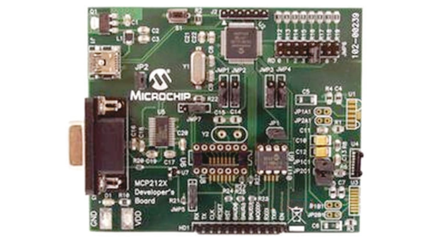
MCP212x IrDA Development Board
The MCP2120/22 Developer’s Board allows for the easy demonstration and development of IrDA applications. The board can be powered via USB or the power test points (VDD and GND). The pre-programmed PIC18F65J50 firmware generates the MCP2122 clock. The Host interface can be connected to the UART driver device (for IrDA to UART operation), for communication over the DB-9 connector or connected to the PIC18F65J50 for stand alone operation. The USB interface signals are fully connected to the PIC18F65J50, so programs can be created where the PIC18F65J50 communicates with the USB Host and the MCP2122. This would allow the board to be used as an IrDA to USB converter.
Mini USB connector (for powering the board)
Onboard +3.3V regulator for powering PIC18F65J50
Hooks for an external regulated DC supply
Jumper to isolate PIC18F65J50 power signal from the rest of board power. This allows the board to operate at voltages higher than +3.3V
RS-232 connector and associated hardware for direct connection to MCP2120 or MCP2122 UART
Twelve-pin header connection to Host UART interface
Four jumpers (3-pin) to select source of UART signals. Either DB-9 connector or the PIC18F65J50
External Clock (from PIC18F65J50’s ECCP1 pin) Jumper
Green power-on indicator LED.
Implemented IR transceiver circuit (two optional optical transceiver circuits implemented but not populated)
Reset switch for PIC18F65J50 device.
ICSP™ header for programming PIC18F65J50
Jumper option for PIC18F65J50 program selection (not installed)
Jumper to select source of MCP2120/22 Reset signal
Jumper to select source of MCP2120 MODE signal
MCP2120/22 SOIC and DIP Footprints (DIP package is the default installation)
Transceivers
คุณสมบัติ / Specifications
คุณสมบัติ | Value |
|---|---|
| Classification | Development Kit |
| Technology | IrDA |